Dual-Arm Robotic Rubik's Cube Solver

A camera, Kociemba's two-phase solver, a MuJoCo model of the rig, and two stepper-driven grippers that can only reach two of the cube's six faces.

Qixuan Huang Yiming Xu Rong Wang Zhuoyang Shen
University of Illinois Urbana-Champaign · ECE 445 Senior Design, Spring 2026
Real robot · 4×

The robot holds a scrambled cube corner-down between two grippers, rolls it through five poses so an overhead camera can see every face, solves the state with Kociemba's two-phase algorithm, and then turns the layers itself. Each gripper can turn only the layer behind the edge it clamps, so most moves start by rolling the whole cube to bring the right layer into reach. A MuJoCo model of the rig runs the same controller and decides every roll, clamp and turn before the motors move.

1000/1000
random scrambles solved by the controller in simulation
21
face turns in the median Kociemba solution
23
whole-cube rolls the arms add to the median solve

System

Planning runs on a host computer; the rig only executes clamp, release and rotate commands.

The mechanism

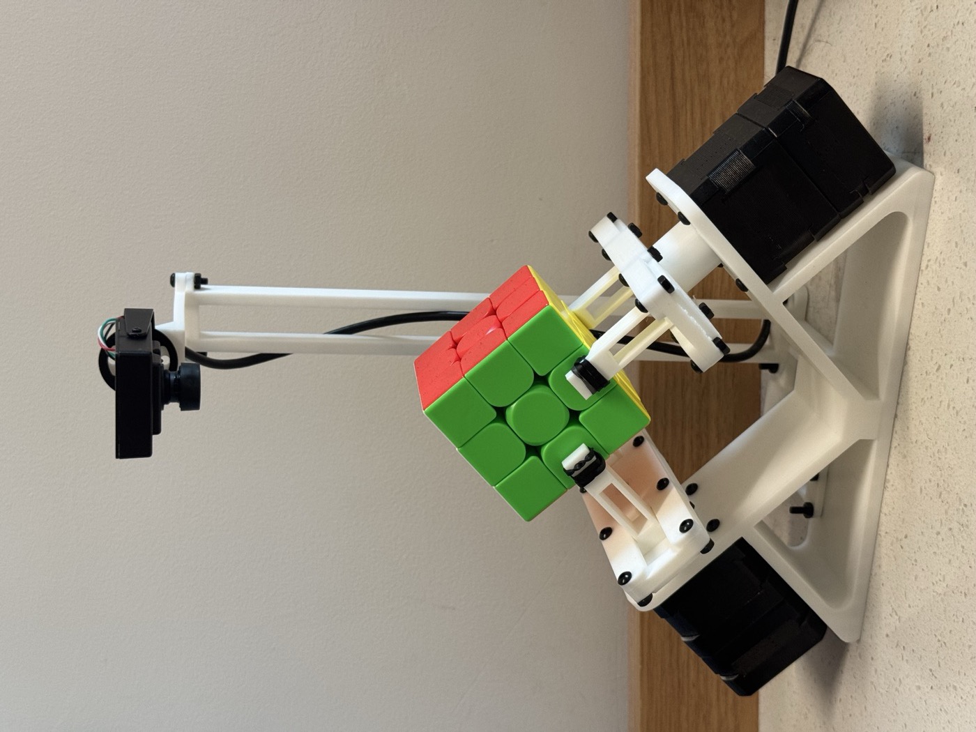
The assembled robot: white printed frame, two black stepper motors, a cube held corner-down between two grippers, and a camera on a mast above
The assembled rig. The overhead camera's mount is part of the frame, so its view of the cube never shifts between scans.
left arm right arm
How a gripper reaches a layer. Each gripper clamps the middle piece of one lower edge (gold). Turning that gripper while the other also holds turns the 9-piece layer behind the edge; turning it while the other is open rolls the whole cube a quarter turn.

With the grippers fixed to the frame, only two of the six layers are within reach at any time. The controller keeps a 3×3 integer matrix from the machine frame to the cube's own frame and updates it after every roll. For each requested move it searches breadth-first over sequences of single-gripper rolls for the shortest one that brings the target layer into a gripper's slot, picking whichever arm needs fewer rolls. Half turns run as two quarter turns, because the wrist only travels ±90°.

  1. ParseRead the next Singmaster token, e.g. R'.
  2. MapConvert it to an axis, a layer and a direction in the cube's frame.
  3. Choose an armThe one whose slot needs fewer rolls to reach that layer.
  4. Roll if neededOne gripper holds and turns; the other opens, then re-clamps.
  5. Turn the layerBoth grippers hold; the active wrist turns 90°.
  6. ResetRelease the active gripper, return its wrist to neutral, clamp both again.

Primitive packets

The interface between the planner and the rig is deliberately small: an ordered list of four kinds of command. The simulation never streams poses or trajectories; whatever the controller decides is written down as these packets, and the same list drives the real motors.

OpFieldsWhat the rig does
CLAMPsideClose one gripper.
RELEASEsideOpen one gripper. Refused unless the other gripper is closed, so the cube is never dropped.
DUAL_HOLDnoneBoth grippers closed; the safe resting state between moves.
ROTATEside, angleDrive one wrist to −90°, 0° or +90°. With the other gripper open this rolls the cube; with both closed it turns a layer.

On the wire, the host sends each packet as one line of JSON carrying both grippers' target state, and blocks until the Arduino answers DONE:

{"L":{"state":1,"angle":1.5708,"action":"ROTATE"},
 "R":{"state":0,"angle":0.0,"action":"HOLD"},
 "t_ms":400}                       // → "DONE"

Two additions came from running the real rig. Stepper clamps slowly lose grip under load, so after each return to a dual hold the bridge sends a short RECLAMP that presses both jaws inward again. And after a release leaves the cube in one gripper, it waits 300 ms while the holding side keeps creeping inward before the next rotation starts.

Reading the cube
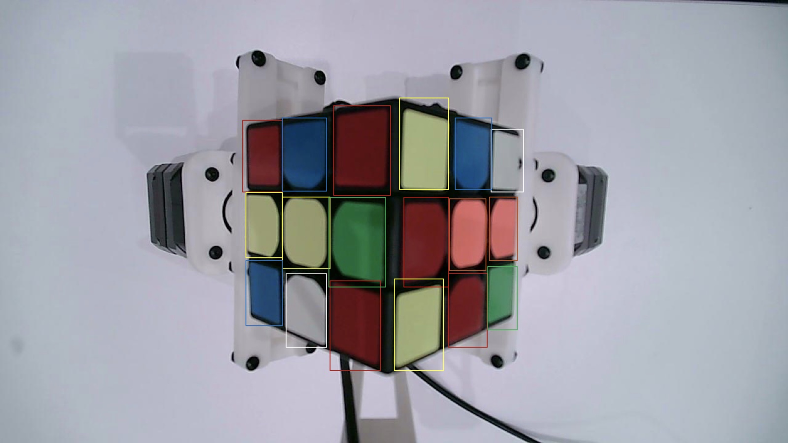
Camera frame of the cube with a coloured bounding box around every visible sticker
One scan frame. YOLOv8-nano boxes every visible sticker as a single class; a KNN classifier then labels each box's colour. Partly hidden stickers are still found.
Training curves for the sticker detector: box, class and DFL losses fall; precision, recall and mAP50 approach 1
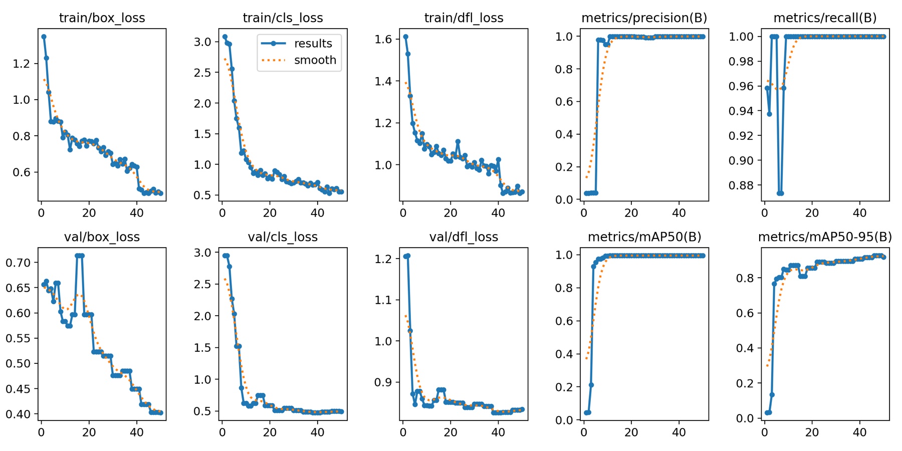
Sticker-detector training (50 epochs, 640×640, AdamW). Our first detector predicted the six colours directly and broke whenever the lighting changed; separating "where is a sticker" from "what colour is it" fixed that.

The camera's auto-exposure and auto-white-balance are switched off at start-up, so colours don't shift when the white arms move through the frame. The scan rolls the cube through five poses, each showing two faces; the ten face views are sorted by position into rows and columns and fused into the 6×3×3 state the solver needs.
Simulation

The model is built from the team's CAD assembly. The arms are reduced to the same four motors the real rig has: a wrist and a clamp on each side.

This is a recording of the MuJoCo model running the robot's controller, played back in your browser with the real CAD meshes. The packet list on the right is exactly what would be sent to the Arduino at that moment. Drag to orbit; hold ctrl or ⌘ and scroll to zoom.

Loading the model…
––
drag to orbit · ctrl/⌘ + scroll to zoom

Packets to the Arduino0

    0 / 0
    scan: five poses, two faces eachplayed so far

    Playback runs at 60 controller steps per second at 1×; it shows the order and geometry of motions, not the real rig's timing. Each "Scan and solve" recording starts from a random 20-move scramble, runs the same five-pose scan as the robot, reads the state, and solves it.

    Rendered in MuJoCo

    Warm-up sequence R U R' U', the first thing we ran end to end. Four face turns become 68 packets: each turn needs one or two rolls first.
    Scan and solve #1: the five-pose scan, then a 21-move Kociemba solution, rendered offscreen from the same run as the interactive recording above.

    Results in simulation

    1000 random 20-move scrambles, each scanned, solved and executed by the controller.

    Solution length

    Face turns in the Kociemba solution

    Quarter turns executed

    Half turns run as two quarter turns on the rig

    Whole-cube rolls per solve

    Extra motions the fixed grippers need

    Serial packets per solve

    Primitive packets plus the bridge's re-clamps and holds

    Show the numbers as a table
    The cube ended solved in all 1000 runs, so the controller's orientation tracking and roll planning hold up on arbitrary states. Rolls are the cost of fixed grippers: a median solve adds 23 of them to 30 quarter turns, and each roll is a release, a one-handed rotation and a re-clamp. That, not the 14 ms the solver takes, is where the real rig's two minutes per solve go.

    Real robot

    Recorded on the integrated rig. The controller and packet stream are the same ones shown above.

    4×
    Full solve. A fully scrambled cube: five-pose scan, Kociemba, then every roll and layer turn. About two minutes in real time.

    What we'd fix next

    Closed-loop motors. The steppers run open-loop. A lost step is invisible to the software, and from then on its idea of the cube no longer matches the real one; encoders, or a quick re-scan after each move, would catch it.

    Contact. The simulation assumes each jaw lands on the centre of an edge piece. On the rig, a few millimetres of misalignment can turn the wrong layer, and the printed jaw faces rely on clamping force; grippier pads would tolerate more error.

    Speed. Every packet waits for the previous one to finish. Starting the next clamp while a rotation settles, and choosing rolls that also shorten later moves, would cut most of the idle time.

    Lighting. The colour classifier was trained under one lighting setup and hasn't been tested under others.

    Side work: a servo-control board

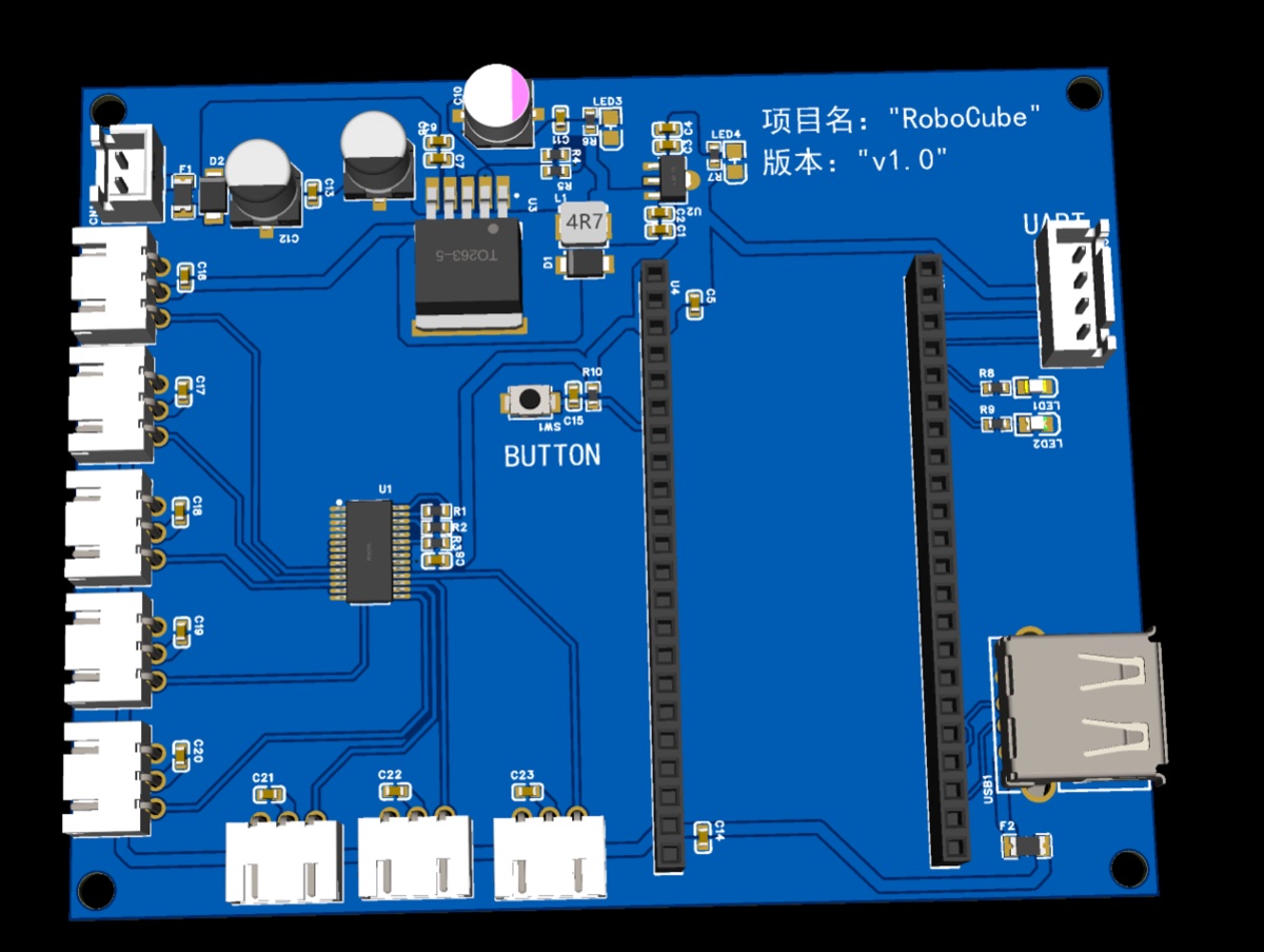
    Zhuoyang also designed a two-layer servo-control board: a PCA9685 16-channel PWM driver on I²C, an XL4015 buck stage for a 5 V servo rail, an AMS1117 3.3 V logic rail, a fused and diode-protected input, and separate servo and logic grounds. Both rails and all 16 PWM channels were verified on the bench.

    The final rig switched to stepper motors driven from an Arduino Nano Every, so this board is not part of the system shown above.

    3D render of the blue two-layer servo-control PCB with servo headers along one edge

    Team

    Simulation, the dual-arm controller and its state machine, the packet format, and the Arduino–MuJoCo bridge.
    Yiming Xu
    Perception: camera setup, the YOLOv8 + KNN pipeline, and assembling the cube state.
    Rong Wang
    Mechanical design and assembly of the dual-arm frame, the stepper drive, and the camera mount.
    Zhuoyang Shen
    Electronics, including the servo-control board.

    BibTeX

    @misc{huang2026cubesolver,
      title  = {Dual-Arm Robotic Rubik's Cube Solver},
      author = {Huang, Qixuan and Xu, Yiming and Wang, Rong and Shen, Zhuoyang},
      year   = {2026},
      note   = {ECE 445 Senior Design Project, University of Illinois Urbana-Champaign}
    }